
Blog

What Is a Wired Push Button and How Does It Work?

A Wired Push Button is a simple control device that sends an electrical signal through a physical cable. Pressing its actuator changes the position of internal contacts. That change can start a motor, activate a doorbell, trigger an alarm, or control industrial equipment. The principle is simple. Small switch, clear action.

Inside the housing, the button usually connects a common terminal to a normally open or normally closed contact. A normally open circuit stays disconnected until someone presses the button. A normally closed circuit remains connected until pressure interrupts it. The connected control system detects this change and responds through a relay, controller, or input module. Wire size, voltage rating, contact capacity, and insulation quality all affect safe performance. A qualified installer should verify these details before connection.

Its value comes from reliability and direct feedback. You can feel the button move and often hear a distinct click. This makes troubleshooting easier, especially beside a machine or access panel. However, a wired design is not automatically safer or better. Poor terminals, loose conductors, moisture, and repeated mechanical stress can cause intermittent operation. That weakness is easy to overlook. This guide explains how a Wired Push Button works, how its terminals are arranged, and where installation choices matter. It also considers practical limitations, because real systems rarely behave as perfectly as diagrams suggest. Manufacturer specifications and appropriate electrical practices should guide every final decision.
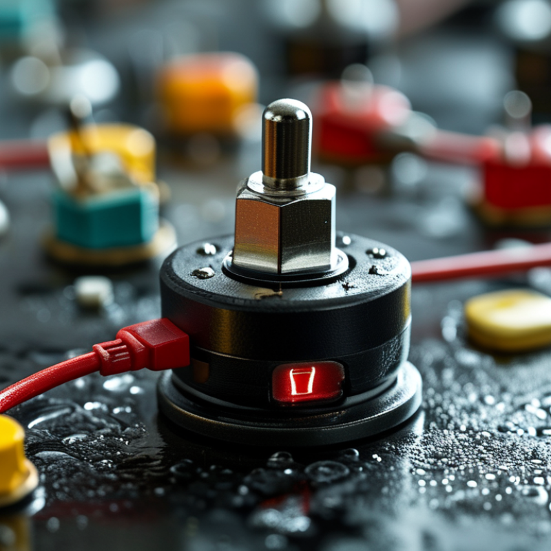
What Is a Wired Push Button and How Does It Work?

What Is a Wired Push Button?

A wired push button is a manually operated electrical switch connected through physical wires. Pressing its actuator changes the circuit between its terminals. Unlike wireless controls, it does not depend on batteries, radio signals, or software pairing. This simple design makes it useful in control panels, door systems, alarms, and small machines.

Most wired push buttons use normally open or normally closed contacts. A normally open button keeps the circuit broken until someone presses it. A normally closed button allows current to flow until pressure interrupts it.

Some buttons are momentary, so the contact changes only while pressed. Others stay in position after activation. The housing may include screw terminals, spring terminals, or solder tabs.

During a practical inspection, a multimeter can confirm the contact behavior before installation. Set it to continuity mode, touch the probes to the terminals, and press the button slowly. The reading should change clearly. It should not flicker repeatedly. That problem may indicate contact bounce, dirt, or a worn mechanism. The label alone is not enough. Check the voltage, current rating, wire size, and enclosure protection. A button rated for a low-voltage signal may fail in a power circuit. I also prefer testing the complete circuit, because a correct switch can still connect to the wrong terminals. Simple does not always mean foolproof.

How the Button’s Internal Mechanism Works

A wired push button converts finger pressure into a controlled electrical change. Inside, the actuator presses a small spring-loaded plunger. That movement shifts a movable contact between fixed terminals. In a normally open design, the circuit stays open until pressure closes it. A normally closed design behaves in reverse.

The spring returns the contact when pressure ends. This creates a momentary signal, not a permanent one. Some assemblies add a latching cam, which keeps the contact in position after release. The internal gap also matters. It helps prevent unwanted current flow and limits arcing during switching. IEC 60947-5-1 defines performance requirements for low-voltage control circuit devices, including contact ratings, insulation, and endurance. These ratings must match the connected load.

Contact bounce is the imperfect part. Mechanical contacts may open and close several times within a few milliseconds. A controller can mistake this noise for repeated commands. Engineers often add software debounce, an RC filter, or a relay interface. The exact method depends on voltage, current, cable length, and switching frequency. The Electrical and Electronic Manufacturers’ Association identifies rated current, insulation voltage, and mechanical life as key selection data. A button rated for 10 A resistive loads may perform poorly with motors or lamps. Those loads create inrush current. A clean-looking button can still hide a weak contact surface. Testing under the real load remains necessary.

What Is a Wired Push Button and How Does It Work? — How the Button’s Internal Mechanism Works

Data Dimension Component or Specification How It Works and Practical Details
Basic Definition Wired push button A manually operated electrical switch that uses external wires to connect or disconnect a circuit. The button normally controls a low-voltage signal, relay input, control circuit, lamp, buzzer, or other electrical load.
Main Actuator Button cap or plunger The part pressed by the user. Mechanical force moves the plunger along its travel path and transfers motion to the internal contact mechanism.
Return Mechanism Compression spring The spring stores energy when the button is pressed and pushes the plunger back after release. In a momentary button, this action restores the normal contact state.
Electrical Contacts Fixed and moving contacts Conductive metal contact surfaces open or close the circuit. When the moving contact touches the fixed contact, electrical current can flow; when separated, the circuit is interrupted.
Contact Configuration Normally open (NO) The contacts remain open when the button is idle. Pressing the button closes the circuit, making this configuration suitable for start signals, call buttons, and trigger inputs.
Contact Configuration Normally closed (NC) The contacts remain closed when the button is idle. Pressing the button opens the circuit, which can be used for stop signals, safety interlocks, or fault-monitoring circuits.
Contact Configuration Changeover contact (SPDT) A common terminal switches between a normally closed terminal and a normally open terminal. This allows one button to transfer a signal between two circuit paths.
Operating Mode Momentary action The electrical state changes only while the button is held down. Once released, the spring returns the contacts to their normal state.
Operating Mode Maintained or latching action A mechanical locking mechanism keeps the button in its new position after pressing. A second press, rotation, or release mechanism returns it to the previous state, depending on the design.
Wiring Method Two-wire connection Two terminals are used to place the button in series with a circuit. For a normally open button, pressing it completes the circuit; for a normally closed button, pressing it breaks the circuit.
Wiring Method Three-wire connection Common, normally open, and normally closed terminals are provided. The circuit designer selects the required contact path without changing the button’s mechanical assembly.
Electrical State Idle state The contacts are in their default position before the button is pressed. The actual electrical condition depends on whether the contact arrangement is normally open, normally closed, or changeover.
Electrical State Actuated state The plunger moves far enough to transfer the internal contact. The circuit either closes, opens, or changes over according to the contact configuration.
Contact Bounce Short transient switching When metal contacts meet or separate, they may make and break contact several times for a brief period before settling. Electronic systems often handle this with software timing, an RC network, a Schmitt trigger, or another debounce circuit.
Circuit Protection Arc and inrush considerations Opening an inductive or high-current load can produce an electrical arc. A relay, fuse, flyback diode for suitable DC coils, snubber, or other suppression device may be needed; the button must be rated for the actual load type.
Common Electrical Ratings Voltage and current rating Ratings vary widely by construction. Small panel buttons may be intended for signal-level circuits, while heavy-duty switches may handle substantially higher current. The correct rating must be checked for AC or DC voltage, continuous current, and load category.
Mechanical Specification Actuation force and travel Actuation force is the force required to change the contact state, while travel is the plunger distance. Both values depend on the spring, contact design, and intended application.
Mechanical Life Number of operating cycles Mechanical life describes how many press-and-release cycles the mechanism can withstand under specified conditions. Electrical life may be lower because contact wear depends on voltage, current, load type, and switching frequency.
Housing and Mounting Panel body and terminals The housing supports the actuator, insulates live parts, and provides mounting features. Terminals may be solder lugs, screw terminals, quick-connect tabs, or wire leads; compatibility depends on the installation method.
Typical Applications Control and signaling circuits Common uses include machine start and stop controls, doorbells, alarms, reset inputs, test panels, access controls, appliance controls, and user-interface signal inputs.
Safe Installation Matching the button to the circuit Verify the contact arrangement, voltage type, load current, inrush behavior, insulation requirements, environmental conditions, and terminal polarity where applicable. Disconnect power before wiring and use suitable overcurrent protection.
Note: Electrical and mechanical ratings are design-dependent. Always use the specifications of the selected switch and the requirements of the connected circuit.

Main Components of a Wired Push Button

A wired push button is a simple control device that sends an electrical signal when pressed. Its main parts work together inside a compact housing. The actuator is the visible button, usually made from durable plastic or metal. Behind it, a spring returns the actuator after each press. This gives the button its familiar tactile response. It feels simple.

The contact block is the electrical core. It contains fixed terminals and a movable contact bridge. In a normally open design, the circuit stays disconnected until pressure moves the bridge into place. Current can then travel through the connected wires. A normally closed design behaves differently. Pressing the button breaks the circuit instead. The terminal screws or wire clamps hold conductors firmly, while the insulating body reduces accidental contact. A small gap matters.

During installation, I check the contact rating, wire size, and enclosure condition before applying power. These details are easy to overlook. The button should also match the circuit’s voltage and current requirements. A loose terminal may create heat, intermittent signals, or unexpected operation. The panel cutout must support the housing without crushing it. Moisture protection matters in damp locations, but its stated rating should never be assumed. Testing the circuit with power removed first is safer and reveals wiring mistakes early. One practical lesson is worth noting: a button may feel mechanically sound while its contacts are already worn. That is why visual inspection alone is not enough.

What Is a Wired Push Button and How Does It Work? - Main Components of a Wired Push Button

A wired push button uses a mechanical actuator to open or close electrical contacts. The waveform below shows the voltage at the input of a typical 5 V pull-up circuit: the input remains high when the button is released and changes to approximately 0 V when the button is pressed.

How the Main Components Work

  • Actuator: The button cap receives the user's force.
  • Spring: Returns the actuator to its original position after release.
  • Electrical contacts: Open or close the circuit as the actuator moves.
  • Terminals: Provide the wired connection to the external circuit.
  • Housing: Supports and protects the internal mechanical and electrical parts.

How to Connect and Install a Wired Push Button

A wired push button is a momentary switch that sends a signal while pressed. Most models use normally open contacts, which close the circuit briefly. Normally closed versions open the circuit instead. Before installation, identify the contact labels, rated voltage, and maximum current. A button designed for control voltage should not directly switch a heavy load.

Turn off power and verify it with a meter. Then route the control wire through suitable conduit or cable protection. Connect the supply wire to the common terminal, and connect the output wire to the load or control input. Tighten each terminal firmly, but avoid crushing thin conductors.

Add strain relief where the cable enters the enclosure. The button should sit securely, with no exposed copper. Small detail. It prevents larger trouble.

For a basic low-voltage circuit, connect the positive control lead to the common terminal and the return lead to the normally open terminal. Pressing the button should complete the circuit. Test continuity before energizing the system, then test operation several times.

NFPA’s Fire Loss in the United States During 2023 report recorded 1,504,500 fires and 29.1 billion dollars in direct property damage, so neat wiring is not merely cosmetic. Use components and enclosures suited to the installation environment, following IEC 60669-1 or applicable local electrical requirements. I still label both ends of every wire. Memory is less reliable than labels.

Common Applications and Selection Considerations

A wired push button is a simple control device with a direct electrical connection. Pressing the actuator changes the contact state, sending a signal to a relay, controller, alarm, or machine circuit. In factories, operators use it for start, stop, reset, jog, and emergency functions. It also appears in building controls, laboratory equipment, access systems, and packaging lines.

Application determines the button’s required design. A dusty workshop may need an IP65 or higher enclosure rating, while a clean control cabinet may need less protection. IEC 60947-5-1 provides requirements for low-voltage control circuit devices, including contact performance and endurance. Selection should also consider voltage, current, contact arrangement, mounting diameter, actuator shape, and expected operating cycles. A guarded button can reduce accidental activation. A raised button may be easier to operate with gloves.

The 2024 MarketsandMarkets Industrial Control Market report projects growth from about 154 billion dollars in 2023 to over 200 billion dollars by 2028. That expansion reflects wider automation demand, but it does not make every button suitable. Real installations are rarely perfect. Temperature, vibration, moisture, and operator habits can change performance. For safety-related functions, designers should follow applicable standards and verify circuit behavior through testing. A low-cost button may fail early under heavy use. A higher-rated component may reduce maintenance, but only when its ratings match the actual circuit. Check the datasheet carefully. Words like “momentary” and “maintained” are not interchangeable.